Selecting a Memory Module for SLC 500

What is EPROM ?
The memory module for the SLC 5/03, SLC 5/04, and SLC 5/05 processors is called Flash EPROM (Flash Erasable Programmable Read Only Memory). Flash EPROMs combine the programming versatility of EEPROMs with the security precautions of UVPROMs. This means that you have the option of leaving your EPROM programs write protected or unprotected. Write protect the EPROM using either your software or a PROM programmer.
The memory modules consist of a Flash EPROM mounted on a circuit board with a connector and plastic housing. There are 2 memory modules available that backup up to 32K or 64K user
memory.

See the table below for details on the Flash EPROM and adapter socket.
Adapter sockets are required when inserting memory modules into commercially available PROM programmer. The memory module fits into the adapter socket and then into a PROM programmer.

Selecting a Memory Module for SLC 500
1. The 1747-M11 Series A memory module can only be used in either an SLC 5/03 Series A
processor or in an SLC 5/03 Series B processor. The 1747-M11 Series B memory module can
only be used in either an SLC 5/03 OS302 or higher, an SLC 5/04 OS401 or higher, or an
SLC 5/05 processor.
2. The 1747-M12 memory module can only be used in either an SLC 5/03 OS302 or higher, an
SLC 5/04 OS401 or higher, or an SLC 5/05 processor.

Tag : PLC Programs; How to select Memory module; Select PLC Memory ; What is EPROM ; ; Allen Bradley Memory ; ; EPROM SLC500

DH-485 Comunication Cable and Isolated Link Couplerm

The link coupler provides a connection for each node. The isolated link coupler electrically isolates the DH-485 communication interface from the processor and peripheral connections.
Electrical-optical isolation is provided to 1500V.

The suggested DH-485 communication cable is Belden #3106A or #9842 cable. The cable is jacketed and shielded with two twisted wire pairs and a drain wire. One pair provides a balanced signal line, and one wire of the other pair is used for a common reference line between all nodes on the network. The shield reduces the effect of electrostatic noise from the
industrial environment on the network communication.

Installing the DH-485 Network

What is DH-485 connection

DH-485 network to pass information between devices on the plant floor. The network monitors process parameters, device parameters, device status, process status and application programs to support data acquisition, data monitoring, program upload/download and supervisory control.
The DH-485 network offers:
• interconnection of 32 devices
• multi-master capability
• token passing access control
• the ability to add or remove nodes without disrupting the network
• maximum network length of 1219 m (4000 ft)


Note
: The SLC 500 Series A (only) processors set the maximum node address to 31 when power is cycled increasing initialization and response time of the network.

The maximum number of communication devices
SLC 500 fixed and SLC 5/01 processors can be selected by two initiators maximum at the same time. Using more than two initiators to select the same SLC 500 fixed and SLC 5/01 processors at the same time can cause communication timeouts.

To install a DH-485, you need tools to strip shielded cable and connect the cable and terminators isolated link Coupler.
Installing the DH-485 with the following tools (or equivalent):


Install DH-485
Tag : DH-485,Install DH-485, what is DH-485, DH-485 connection, How to connect DH-485, Install DH-485

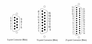
Types of RS-232 Connectors


The figure below show male connectors, and their pinout locations,
for Allen-Bradley devices.

Types of RS-232 Connectors

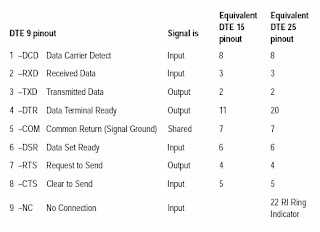
DTE Pinout

Channel 0 is configured as DTE for all SLC 5/03, SLC 5/04, and SLC 5/05 processors. The pinouts are the same as the 9-pin AT port.

Types of RS-232 Connectors

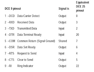
DCE Pinout

Devices such as a modem are Types of RS-232 Connectors. The pinouts on these terminals are wired to interface with DTE.
Types of RS-232 ConnectorsNote : DCE signal names are viewed from a DTE perspective.

Tag : Type of RS-232, DCE Pin out, DTE Pin out, DTE, DCE

RS-232 Communication for SLC500

The RS-232 Communication channel on the SLC 5/03, SLC 5/04, and SLC 5/05 processors supports four protocols:
• Full-Duplex DF1 (default)
• Half-Duplex DF1 (SCADA)
• DH-485
• ASCII Communications

The SLC and PLC products detailed in this appendix that communicate over the RS-232 Communication interface also use the DF1 serial communication protocol. DF1 protocol delimits messages, controls message flow, detects and signals errors, and retries after errors are detected.

The SLC 5/03, SLC 5/04, and SLC 5/05 processors can communicate by means of the RS-232 Communication port,
channel 0. Channel 0 supports DF1 full-duplex protocol and DF1 half-duplex master and slave protocol, DH485 protocol , as well as ASCII communications. Refer to your programming software user manual for information on configuring the RS-232 Communication port, channel 0.

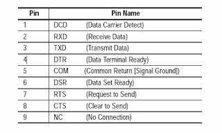
Channel 0 provides a minimum of 500V dc isolation between the I/O signals and the logic ground of the SLC 5/03, SLC 5/04, and SLC 5/05 processors. The channel is a 9-pin D-shell. The table below provides a description of each of the pins.

RS-232 CommunicationTag : RS-232 Communication, RS-232 , RS-232 Communication for SLC 500, RS-232 interface, RS-232 Connector

Replacing Battery of Allen Bradley PLC.


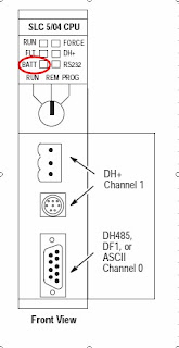
SLC 5/03, SLC 5/04, or SLC 5/05 processor provides back-up power for RAM by replaceable lithium PLC Battery. This PLC Battery provides back-up for approximately 2 years. A BATT LED on the
will alerts when the PLC Battery voltage was drop under a threshold level.

Replace PLC Battery Note : Please see PLC Battery warning in this pic.

Will safety for your equipment, if replace the lithium PLC Battery follow these steps:

1. Remove power from the SLC 500 power supply.

Note : Do not remove the processor from the SLC 500 chassis until all power is removed from the SLC 500 power supply.

2. Remove the processor from the chassis by pressing the retainer clips at both the top and bottom of the module and slide it out.

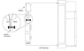
3. Unplug the PLC Battery connector. Refer to the figure below for PLC Battery connector location.

Replace PLC BatteryNote : PLC Battery can back up Data in RAM at least 30 minutes.

4. Remove the PLC Battery from the retaining clips.

5. Insert a new PLC Battery into the PLC Battery retaining clips.

6. Plug the PLC Battery connector into the socket.

7. Re-insert the module into the SLC 500 chassis.

8. Restore power to the SLC 500 power supply.

Tag : PLC Battery, Replace PLC Battery, SLC 5/04 Battery, SLC 5/05 Battery, SLC 5/03 Battery, Replace Allen Bradley battery, Allen Bradley PLC Battery, PLC Battery


Key switch for Allen Bradley PLC

The SLC 5/03, SLC 5/04, and SLC 5/05 processors include a 3-position Key Switch on the front panel that lets you select one of three modes of operation: Run, Program, and Remote. You can
remove the key in each of the three positions.

Note : The SLC 5/01 and SLC 5/02 processors do not have a Key Switch. Therefore, all modes must be changed via the communication channels.

PLC ProgramsPLC Programs


RU
N Position

This position places the processor in the Run mode. The processor
scans/executes the ladder program, monitors input devices, energizes
output devices, and acts on enabled I/O forces. You can only change
the processor mode by changing the Key Switch position. You cannot
perform online program editing.
To change the processor mode to Run, toggle the Key Switch from
PROG or REM to RUN. When the Key Switch is left in the RUN
position, you cannot use a programmer/operator interface device to
change the processor mode.

PROG Position

This position places the processor in the Program mode. The
processor does not scan/execute the ladder program, and the
controller outputs are de-energized. You can perform online
program editing. You can only change the processor mode by
changing the Key Switch position.

To change the processor mode to Program, toggle the Key Switch
from REM or RUN to PROG. When the Key Switch is left in the
PROG position, you cannot use a programmer/operator interface
device to change the processor mode.

REM Position

This position places the processor in the Remote mode: either the
REMote Run, REMote Program, or REMote Test mode. You can
change the processor mode by changing the Key Switch position or by
changing the mode from a programmer/operator interface device.
You can perform online program editing in this position.
To change the processor mode to REM, toggle the Key Switch from
RUN or PROG to REM. When the Key Switch is in the REM position,
you can use a programmer/operator interface device to change the
processor mode.

Tag : Key Switch,Key switch position, PLC Key switch, Allen bradley Key switch

Enter your email address:

Delivered by FeedBurner